
Compressor Room Layout and Piping Pressure Drop: A Design Guide
Design the room around three numbers. Total pressure drop from the compressor outlet to the furthest point of use should stay at or below 0.3 bar. Air velocity in the main header should stay at or below 6 m/s. Clearance in front of every panel, filter and drain that somebody has to reach should be at least 1.2 m. Pipe material, receiver volume, dryer position and ventilation all follow from those three constraints plus the site ambient. If a layout cannot meet them on paper, it will not meet them in the building either.
What pressure drop actually costs
A compressed air system is usually commissioned by raising the setpoint until the most distant tool behaves, which quietly converts a piping problem into a permanent electricity bill. The relationship is roughly linear and easy to remember: every extra bar of discharge pressure you carry to overcome line losses costs about 6–8 % of shaft power at the same delivered flow.
| Unnecessary discharge pressure | Indicative extra shaft power | What it usually means |
|---|---|---|
| 0.5 bar | 3–4 % | One clogged coalescing element nobody replaced |
| 1.0 bar | 6–8 % | Undersized header plus a 15 m hose at the tool |
| 1.5 bar | 9–11 % | Dryer and filters without bypass, all measured together |
| 2.0 bar | 12–15 % | A ring main built in two diameters and never balanced |
The correct sequence is therefore: measure the pressure at the tool while it is working, measure it at the compressor discharge at the same moment, and treat the difference as a design defect with a cost. Correcting the defect and then lowering the setpoint is what converts pipe diameter into kilowatt-hours. For the load-side version of the same arithmetic, see how partial-load VSD savings are actually calculated.
Velocity decides pipe size, not the pressure rating
Schedule 40 steel rated at 16 bar will not burst at 8 bar, which is why so many installations are piped in a size chosen for mechanical convenience rather than for flow. Pressure rating decides whether the pipe survives; velocity decides whether the system is efficient, quiet and dry. Above roughly 6 m/s in a main header, entrained condensate stops draining to the low points and starts travelling with the air, and friction loss rises with the square of velocity.
| Free air delivery | Recommended header | Velocity at 7 bar g | Typical drop, 100 m run |
|---|---|---|---|
| 1 m³/min (35 cfm) | DN25 (1″) | 6.4 m/s | 0.09 bar |
| 3 m³/min (106 cfm) | DN40 (1½”) | 6.0 m/s | 0.08 bar |
| 6 m³/min (212 cfm) | DN50 (2″) | 6.4 m/s | 0.08 bar |
| 10 m³/min (353 cfm) | DN80 (3″) | 4.1 m/s | 0.04 bar |
| 20 m³/min (706 cfm) | DN100 (4″) | 5.3 m/s | 0.04 bar |
| 30 m³/min (1,060 cfm) | DN125 (5″) | 5.1 m/s | 0.03 bar |
| 40 m³/min (1,413 cfm) | DN150 (6″) | 4.7 m/s | 0.03 bar |
Two structural choices do more for the budget than any single diameter. First, build the header as a ring or loop rather than a single trunk: air can reach a heavy consumer from two directions, which halves the velocity in each leg and roughly quarters the friction loss. Second, take each drop off the top of the header with a tee and a short riser, never off the bottom, so condensate continues along the main instead of turning into the tool.
Fittings are not free. Every bend and valve adds an equivalent length of straight pipe, and the totals surprise people who count only metres:
- 90° elbow, standard radius: about 30 pipe diameters each
- 45° elbow: about 16 diameters
- Gate valve, fully open: about 7 diameters; globe valve: about 340 diameters
Zone the room before you draw the pipes
Rooms fail for reasons that have nothing to do with the compressor: the machine recirculates its own cooling air, the dryer sits in the hottest corner, and the filters are installed at chest height behind a pallet stack. Zoning the space first makes those failures structurally impossible.
| Zone | Contents | Minimum clearance to keep |
|---|---|---|
| Compressor bay | Machine, isolator, drain point | 1.2 m front, 0.8 m sides, 1.0 m above for cooling air |
| Receiver | Air receiver, safety valve, drain | 0.6 m around the shell, valve handle reachable |
| Treatment bay | Dryer, pre-filter, after-filter, bypass | 1.0 m front for element changes, room to open the bypass |
| Distribution | Header, isolation valves, drops | 0.5 m from any wall the header runs along |
| Service aisle | Consumables, hose, tools | A straight run wide enough for a trolley, not a corner |
Put the treatment bay downstream of the compressor and before the header, never at the far end of the building where a forgotten dryer will happily condense water into the mains. If the dryer has to sit outdoors or in an unheated annex, check the manufacturer’s ambient range first — a refrigerated dryer rated at 38 °C ambient is a different machine at 46 °C, and the selection process for that is covered in choosing a dryer by pressure dew point.
Heat is the second layout problem
Roughly 94 % of the shaft power that goes into an oil-flooded screw compressor leaves as heat. Only a few percent is recoverable as compressed air energy. A 75 kW machine therefore releases something like 70 kW into the room, and a room that cannot remove it will push the machine into a high-discharge-temperature trip on the hottest week of the year — the same week the plant is busiest.
The ventilation airflow needed for a 10 K temperature rise works out at roughly 0.083 m³/s per kW rejected, or about 300 m³/h per kW. For that 75 kW machine, budget around 21,000 m³/h of air through the room. Duct the intake low and the extract high, on opposite walls, and check that the extract does not feed the intake of the same or a neighbouring machine.
- Never recirculate cooling air to “save” heating in winter — without a designed heat-recovery duct it becomes a hot-air trap
- Leave the 1 m above the machine clear; a canopy over the enclosure is the commonest cause of nuisance trips
- Decide heat recovery at layout stage: 70–90 °C hot water needs pipe routes and a buffer tank that cannot be retrofitted cheaply
Machines built for high pressure reject more intercooler heat per unit of free air, which is one reason a two-stage 16 bar machine needs a more careful room than an 8 bar unit of the same motor size.
Receiver, dryer and filter sequence
The order of components matters more than their individual quality. Condensate should be removed while the air is still hot enough to carry it, and filtration should protect whatever sits downstream rather than sit wherever there was space.
| Position | Component | Why it is there |
|---|---|---|
| 1 | Wet receiver after the compressor | Knocks out bulk condensate, damps pulsation and gives the dryer a stable inlet |
| 2 | Cyclone or bulk water separator | Removes liquid before the coalescing element has to |
| 3 | Coalescing pre-filter | Protects the dryer from oil aerosol; a fouled refrigerated dryer is an oil problem, not a refrigerant problem |
| 4 | Refrigerated or desiccant dryer | Sets the pressure dew point the rest of the system is designed around |
| 5 | Fine coalescing after-filter | Catches desiccant dust or carry-over before the header |
| 6 | Dry receiver, then header | Buffers demand spikes so the compressor is not chasing every tool |
As a starting point allow 0.3 m³ of receiver per m³/min of free air delivery on a steady load, and around 0.5 m³ where the load swings or the machine is variable-speed. Size it on the largest short-term demand, the same basis used to match a machine to a real duty cycle.
The details that decide whether it still works in year three
Almost every new installation runs well. The difference between systems that hold their efficiency and systems that lose a bar a year is in the drainage and isolation details, which cost little at build stage and a great deal afterwards.
- Slope the header 1 : 100 away from the compressor and fit drip legs with drains at every low point, at the base of every riser and at the end of the main
- Install a bypass with isolation valves around the dryer and each filter, so an element change or a dryer fault does not stop production — an unbypassed dryer is the reason plants run at 9 bar
- Use automatic drains with a strainer and a manual override, and pipe the discharge somewhere it can be seen: a blocked drain announces itself as water in the tool
- Record the differential pressure across each filter at commissioning and write it on the housing — that number, not a calendar, says when the element is done
Auditing an existing installation in six steps
- 1. Log pressure at the discharge and at the two most distant tools at the same moment, under normal load, over a full shift
- 2. Split the difference into segments: dryer and filters measured across each, header, drops, hoses and fittings
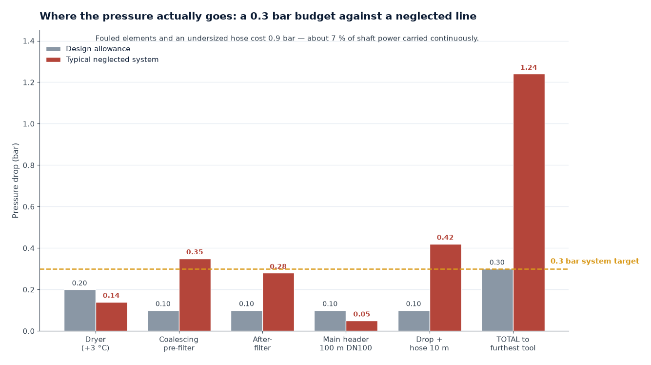
- 3. Compare each segment with the budget — 0.2 bar dryer, 0.1–0.2 bar per element, 0.1 bar main, 0.1 bar drop and hose
- 4. Check velocity from measured flow, not nameplate: a header right for one machine is often wrong for three
- 5. Look for cheap losses first — throttled valves, a 6 mm hose on a 40 cfm tool, filters with the element fitted backwards
- 6. Only then lower the setpoint in 0.2 bar steps and confirm the furthest tool still performs at worst-case demand
What to specify so the layout survives procurement
Pressure drop is decided twice: once by the engineer who draws it, once by whoever buys the pipe. Naming the design velocity, the drop budget per segment and the bypass requirement keeps the second decision from undoing the first. Send the duty — pressure, free air delivery, ambient, running hours and the layout if one exists — and ask for the pressure budget component by component; a quotation that lists a discharge pressure without a downstream allowance is incomplete. Our engineering team works through this with the two-stage and single-stage ranges on exactly this basis, and the custom system route when the room itself is the constraint.
Frequently asked questions
What is an acceptable total pressure drop in a compressed air system?
0.3 bar from the compressor discharge to the furthest point of use is a sound design target, split roughly as 0.2 bar for the dryer, 0.1–0.2 bar per filter element in clean condition, 0.1 bar for the main header and 0.1 bar for the drop and the hose. Where the process is sensitive, 0.2 bar is achievable with a ring header and generously sized drops; where a single oversized hose feeds a large tool, 0.5 bar is common and should be fixed before anyone touches the setpoint.
Is 6 m/s really the limit for a main header?
It is the practical limit for air that has to stay dry and quiet. Between 6 and 10 m/s the loss is still tolerable on short runs, but condensate that would otherwise drain starts to be carried along, and noise at fittings rises sharply. Above about 15 m/s in a drop you can hear the pipe work and the pressure at the tool becomes load-dependent. Ring headers let you keep velocity low without buying the next pipe size up.
How much ventilation does a compressor room need?
Size it on rejected heat, not on room volume: about 300 m³/h of air per kW of rejected heat for a 10 K rise, which for an oil-flooded machine is close to the shaft power. A 75 kW machine therefore needs roughly 21,000 m³/h. Duct the intake low, the extract high and on the opposite side, and verify the extract is not recirculated into the intake. Where the room cannot be opened up, heat recovery to hot water is usually the better answer than more fans.
Can a pipe run outdoors?
Yes, with two consequences that must be designed for: the air cools, so any moisture still in it condenses in the pipe, and the pipe needs draining and freeze protection. If the line is exposed to sub-zero ambient, the pressure dew point leaving the dryer has to be below the coldest pipe temperature the line will see, which usually moves the specification from a refrigerated dryer to a desiccant type.
Answers apply to oil-flooded rotary screw installations with standard filtration; site-specific limits always come from the manual of the unit supplied and from the process standard for the application.
Planning a compressor room or fixing a pressure problem?
Send us the duty — discharge pressure, required free air delivery, ambient conditions, annual running hours — and a sketch of the room if you have one. We will come back with a pressure budget and a machine recommendation that matches it.