
Air Receiver Sizing: How Much Storage a Screw Compressor Really Needs
Storage is the only part of a compressed air system that can absorb a demand spike without changing compressor output, and it is routinely sized by folklore. The usable air in a receiver is the volume multiplied by the pressure band the controls allow, divided by atmospheric pressure — nothing else. A 2 m³ receiver with a 1.5 bar band hands over about 3 m³ of free air, roughly 105 cubic feet, which on a 10 m³/min machine is eighteen seconds of buffer. Whether eighteen seconds is enough depends entirely on what you expect the storage to do.
What the receiver is actually doing
Four jobs get conflated, and they do not need the same volume. Naming them separately is what turns a guess into a size:
- Cycle damping. On load/unload and start/stop control the receiver gives the machine somewhere to put air between cut-out and cut-in, which is what limits starts per hour and keeps the motor and contactors inside their duty.
- Spike absorption. A cylinder, a blow-off or a baghouse pulse draws far more than average flow for a second or two. Storage serves that peak locally so the header does not dip and the compressor does not chase it.
- Control stability. A small reservoir of pressurised air ahead of the header stops short demand events from dragging the whole system through a pressure swing that the controller reads as a load change.
- Condensate and cooling. A wet receiver slows the air down, drops bulk water and gives the drain somewhere useful to work — a function of placement as much as of size.
The formula, and what it really says
Usable free air per drawdown equals receiver volume × pressure band ÷ atmospheric pressure. In SI: V(m³) × ΔP(bar) / 1.013 gives free air in m³. In imperial, V(ft³) × ΔP(psi) / 14.7 gives free air in ft³. Rearranged for sizing, the volume you need for a given event is the free air demanded × 1.013 ÷ the pressure band you are willing to spend. The band is the lever: doubling it halves the vessel. That is why a receiver sized against a 0.3 bar band looks absurdly large, and the same receiver against a 1.5 bar band looks almost small.
The pressure band is bounded from above by what the end uses tolerate and from below by the compressor’s own control limits. Most industrial headers work between 6.5 and 7.5 bar gauge without complaint; a plant that insists on 7.0 ± 0.1 bar has thrown away most of its storage and will pay for it either in vessel size or in pressure swings.
| Event to ride through | Free air needed | Band 0.5 bar | Band 1.5 bar |
|---|---|---|---|
| One 200 l cylinder fill, 6 to 4 bar | 0.4 m³ | 0.8 m³ | 0.3 m³ |
| Baghouse pulse, 300 cfm for 2 s | 0.28 m³ | 0.6 m³ | 0.2 m³ |
| Load/unload idle time of 60 s at 5 cfm | 8.5 m³ | 17 m³ | 5.7 m³ |
| Compressor trip, 90 s at 100 cfm | 4.2 m³ | 8.5 m³ | 2.8 m³ |
Storage by control mode
The practical ranges below are what a sizing exercise tends to land on once the band is fixed. They are expressed per m³/min of compressor free air delivery, so they scale with the machine rather than with a catalogue number. One US gallon per cfm, the oldest rule in the trade, is about 134 litres per m³/min — a floor, not a target.
| Control mode | Receiver volume | Why |
|---|---|---|
| VSD, modulating, 0.3–0.5 bar band | 100–150 l per m³/min | The drive covers the modulation; storage only smooths events |
| Load/unload, 1 bar band | 350–500 l per m³/min | Enough to keep cycling inside motor start and contactor limits |
| Load/unload, 1.5–2 bar band | 450–650 l per m³/min | Wider band, fewer cycles, smaller vessel for the same buffer |
| Start/stop, small unit | 550–800 l per m³/min | Starts per hour are the binding constraint, not energy |
| Demand spikes above 30 % of average | 700–1,000 l per m³/min | Local storage protects the header and the trim machine |
Sizing a load/unload machine, step by step
Take a 10 m³/min unit running a 7.0 to 8.2 bar band with a 500 litre receiver and a light overnight load of 1 m³/min. Usable air per cycle is 0.5 × 1.2 / 1.013, about 0.59 m³, so at 1 m³/min the machine unloads for roughly 35 seconds and loads for about 5. That is 90 cycles an hour — far beyond what most load/unload controls and contactors are happy with, and the reason a plant in this condition reports pressure swings at night. Doubling the receiver to 1,000 litres halves the cycle rate; widening the band to 1.8 bar does the same again without buying steel. Either change is cheaper than the consequences of 90 cycles an hour, and the arithmetic tells you which one fits the site.
The same calculation explains why storage does not fix a leak problem. Leaks are a continuous load, not a spike: more volume lengthens the unloaded time of each cycle, but the loaded fraction barely moves, because the air still leaves through the same holes. Storage manages events. It does not remove demand.
VSD machines need less, but not none
A variable-speed unit modulates to match demand, so it does not need volume to limit starts. It still needs some, for two reasons. The drive has a minimum speed below which it must load and unload like a fixed-speed machine, and at low demand the unit will sit in that region cycling unless there is storage to smooth it. And the pressure transducer sits on the machine, not on the header: a spike at the far end of the system is invisible until the local pressure collapses, so a modest receiver near the large intermittent users does more for stability than extra volume at the compressor.
Placement: wet storage, dry storage, and the pressure you lose between them
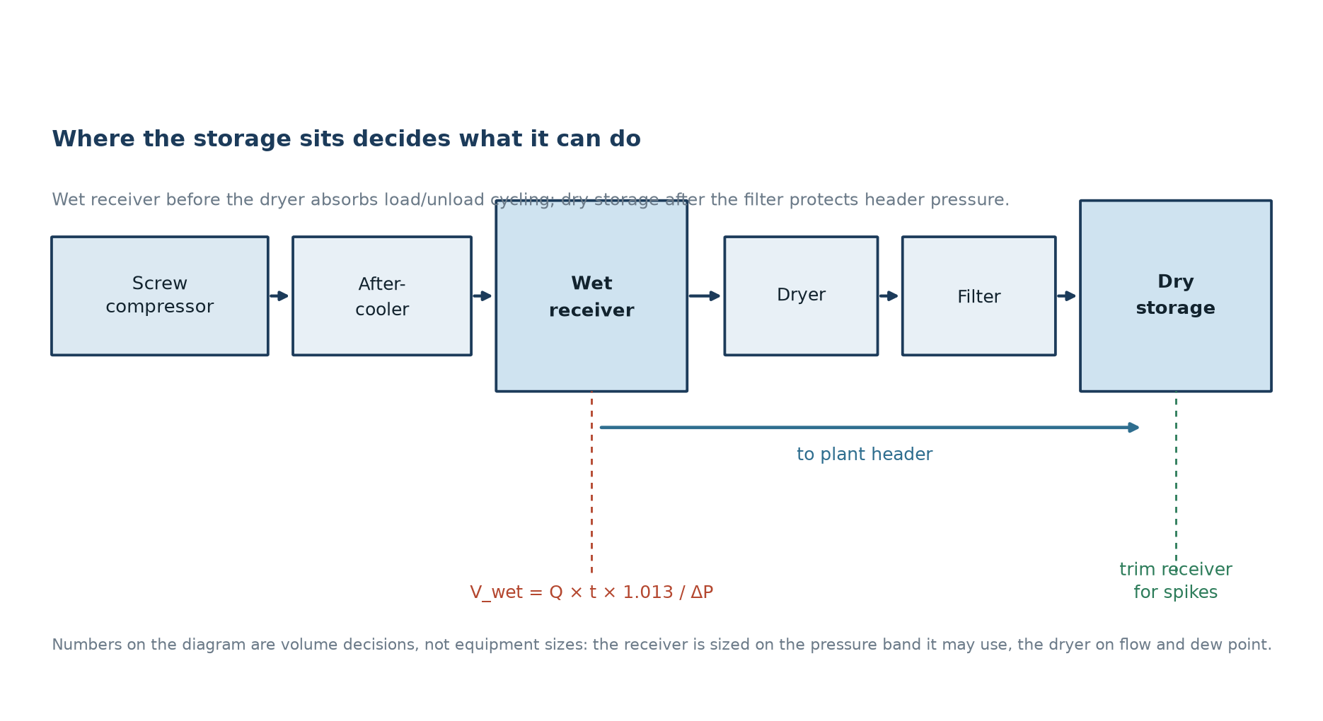
Position decides function. A receiver between the compressor and the dryer — a wet receiver — slows the air, drops bulk condensate and gives the machine a buffer against its own cycling. A receiver after the dryer and filters — dry storage — is what actually protects header pressure, because everything upstream of it has already spent its pressure drop, which is where dryer selection starts to matter. Putting the only receiver downstream of a dryer and a pair of filters means the buffer is connected to the compressor through two restrictions, and fast events arrive at the vessel already partly formed. Two smaller vessels in the right places usually beat one large one in the wrong place.
Also check what the storage drains. A receiver full of condensate has less effective volume and sends water downstream into the dryer and the header. A working automatic drain, sized and set to discharge the condensate and not the air, is part of the storage design, not an accessory.
Mistakes that make a correctly sized receiver useless
- Band set too narrow. A controller set to 7.0/7.2 bar on a 2 m³ receiver holds a sixth of the usable air of a 7.0/8.2 setting and cycles six times as often.
- Restriction between storage and load. Undersized dryers, clogged filter elements and long small-bore runs turn a large vessel into a distant one.
- No check valve at the compressor discharge. Air flows back through an unloaded machine and the storage empties into a machine that is not pumping.
- Sizing on average flow. Storage exists for peaks; averages never needed it and never size it, and an average also hides the trim machine that runs for a few cfm.
- Using storage to postpone repairs. Volume hides leaks for a while, then the compressors run loaded continuously and the energy bill is the diagnosis.
Getting the number right the first time
Size storage from three inputs the site already has: the control mode and its pressure band, the largest event that must be ridden through, and the flow at which the machine may cycle. Everything else — vessel diameter, orientation, nozzle sizes, drain type — follows the applicable pressure-vessel code for the installation. What the arithmetic will not tolerate is a receiver chosen because it was the size on the last project, or a band narrowed after commissioning because someone wanted a tidier pressure gauge.
Frequently asked questions
Is one gallon per cfm enough?
It is a floor for a small fixed-speed machine with a wide band. It is not enough for a load/unload unit that has to limit starts, and it is nowhere near enough for a system with a large intermittent user.
Does a bigger receiver reduce energy consumption?
Only indirectly, by letting the machine run in a more efficient part of its cycle and by preventing unnecessary starts and pressure setpoint increases. Storage does not create air and does not remove leakage.
Should the receiver be upstream or downstream of the dryer?
Both, in most industrial systems: a wet receiver ahead of the dryer for cycling, condensate and cooling, and dry storage after the filters to protect header pressure. One vessel in one place serves one of those jobs well at best.
How much band can we actually use?
Whatever the end uses tolerate with margin. Most plants can run 6.5 to 7.5 bar gauge without changing tool behaviour, and that full bar is worth roughly 0.6 m³ of free air per cubic metre of receiver volume.
Does storage help with a VSD compressor?
Yes, at the low-demand end where the drive reaches minimum speed, and for local spikes that the machine’s own transducer cannot see. It is not needed to limit motor starts in normal modulating operation.
Answers apply to oil-flooded rotary screw installations with standard filtration; site-specific limits always come from the manual of the unit supplied and from the process standard for the application.
A receiver size you can defend?
Send the compressor capacity and control mode, the pressure band you can live with and the biggest demand event on site. We will run the drawdown arithmetic, place wet and dry storage, and tell you whether a vessel, a control change or a leak repair is the answer.