
Compressed Air Leak Survey: Measuring the Demand You Already Pay For
A leak survey answers one question before it answers any other: how much of the air leaving your compressors is doing work? You get that number without an ultrasonic detector, in about an hour, from a stopwatch and a pressure log. Stop production, leave the compressor running, and watch how often it loads. If it spends a third of its time loaded with nothing running, a third of your compressed air is leaking out of fittings, hoses and open drains. Everything after that — repairing, re-piping, adding storage, resizing — follows from the number you just measured.
Why the leak survey comes before any sizing decision
Leak loads of 20 to 40 % of total demand are ordinary in plants that have never run a programme, and the failure mode is always the same: demand creeps up, the compressor runs loaded longer, someone concludes the machine is too small, and a larger unit is installed. The leaks do not go away. They simply consume the new capacity at the same percentage, and the site buys a bigger machine to feed the same holes. The same logic wrecks control retrofits: a variable-speed upgrade or a sequencer sized against a demand figure that is a third leakage will deliver a fraction of the saving it was sold on, because the leak load is flat and never modulates. Measure the composition of demand first, then decide what equipment is worth changing.
Measurement one: the no-load cycling test
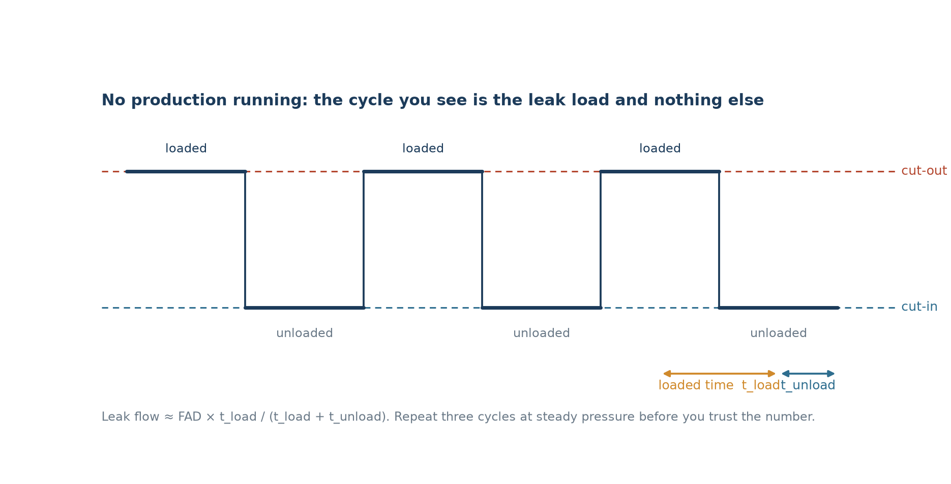
Run the plant with all production stopped, all end uses closed, and the compressor in its normal load/unload control. Log discharge pressure at one-second resolution for at least three complete cycles, then work out the loaded fraction. The leak flow is the compressor’s free air delivery multiplied by that fraction. On a unit delivering 353 cfm (10 m³/min) that loads for 22 seconds and unloads for 48, the leak load is 353 × 22 / 70, about 111 cfm. That is 31 % of capacity, and it is the flow that has to leave the system through the pressure band it is cycling across.
| Measured leak share | What it usually means | What to do next |
|---|---|---|
| Under 10 % | A maintained plant with an active programme | Repeat the test twice a year; keep tagging |
| 10–20 % | Normal wear: couplings, drains, ageing hose | Locate and repair, then re-measure in a month |
| 20–35 % | No ownership of leaks; repairs are reactive | Formal survey, area by area, with a tag register |
| Above 35 % | Leaks are the largest single end use | Repair before any capacity or control investment |
Two conditions make the test honest. First, the compressor must be the only one running and the system must be genuinely idle — a single production cell left on will bury the leak signal. Second, the unit must reach cut-out and stay there for a measurable time; if it never unloads, the leaks are larger than the compressor, and you need the pressure-decay test to quantify them.
Measurement two: pressure decay on an isolated section
Close the section off, pump it to normal working pressure, shut the compressor, and time the fall. The free air that escaped is the volume of the section multiplied by the change in absolute pressure, and dividing by the test time gives the leak rate. A 2,000 litre receiver plus its piping falling from 8.0 to 7.5 bar absolute in four minutes loses 2,000 × 0.5 / 1.013, roughly 987 litres of free air, which is about 8.7 cfm. Use the absolute pressures, not the gauge readings: a receiver at 7 bar gauge holds about eight atmospheres, and using gauge figures understates the leak by that factor.
The decay method is the only practical way to size a leak that exceeds compressor capacity, and it is also the right tool for a zone-by-zone breakdown — plant main, departmental sub-header, end-of-line drop. Work down the tree and the numbers reconcile: the sum of the branches should land near the trunk. When they do not, the difference is usually a shut-off valve that does not shut, or a leak on a section you believed was isolated.
Measurement three: finding the individual holes
Only now is the ultrasonic detector useful. It locates and confirms, it does not quantify. Sweep at walking pace with the receiver in the 40 kHz band, confirm each candidate by the sound signature and by a soap test on pressurised joints, and log it. The register matters more than the sweep: tag, area, fitting type, estimated size, date found, date repaired. Leaks are not evenly distributed — they cluster where vibration, thermal cycling and repeated connection meet:
- Push-in tube fittings on solenoid valve manifolds and FRL units — the single largest count in most surveys.
- Flexible hoses at tool drops, especially where the hose is used as a handle.
- Condensate drains stuck open, or timer drains set to open for longer than the condensate takes to leave.
- Threaded joints and quick couplers that were sealed once and never checked again.
- Cylinder rod seals and valve exhausts on actuators that are worn rather than leaking at a fitting.
What a hole is actually worth
Leak flow through a sharp-edged orifice at 7 bar gauge follows the choked-flow relation, and the arithmetic is uncomfortable: flow scales with the square of the diameter, so doubling a hole multiplies the waste by four. Energy follows at roughly 0.175 kW per scfm on a typical oil-injected unit at that pressure, and the hours are the running hours of the compressor, not the production hours.
| Hole diameter | Leak flow at 7 bar(g) | Shaft power | 8,000 h a year |
|---|---|---|---|
| 1 mm | 2 scfm | 0.35 kW | 2,800 kWh |
| 2 mm | 8 scfm | 1.4 kW | 11,200 kWh |
| 3 mm | 18 scfm | 3.2 kW | 25,200 kWh |
| 5 mm | 50 scfm | 8.8 kW | 70,000 kWh |
| 8 mm | 128 scfm | 22.4 kW | 179,000 kWh |
Two caveats keep this honest. The flow depends on upstream absolute pressure, so a leak on a 10 bar system passes about 30 % more air than the same hole at 7 bar. And the energy figure is power at the compressor shaft for the air that leaked; if the unit was unloading anyway, part of that air was cheap. The saving is real on a loaded machine, which is the case in almost every plant that has a leak problem worth surveying.
Pressure is the multiplier, not the hole
Leak flow is proportional to absolute pressure, so the cheapest single intervention is often to run the system lower. Dropping a header from 7 to 6 bar cuts every leak in the plant by roughly 12 % at once, and it cuts artificial demand — the extra flow created by regulators that are set higher than the tools need — by the same order. The catch is that the reduction only holds if the piping can deliver the flow at the lower pressure without excessive drop: a header that is already losing a bar through undersized mains and elbows cannot afford another one. Check the pressure profile at full demand before turning anything down, and look at the drop across dryers and filters as part of the same measurement. Site conditions that change delivered flow — hot ambient, altitude, a supply that sags under load — move the baseline too.
Turning the survey into a repair order
Rank by cost, not by count. A single 5 mm hole is worth more than thirty 1 mm fittings, and the point of the register is to make that visible so the first day of work goes to the leaks that matter. A sequence that survives contact with a maintenance department:
- Week one: the ten largest leaks, plus every drain that is stuck open. This is usually a third of the total leak load for a day of work.
- Week two: leaks on lines that are pressurised around the clock, including weekends — those run the longest hours per repair.
- Week three: fittings on the highest-pressure zone, where each hole costs the most flow.
- Ongoing: a tag register with an owner and a monthly sweep of one area, so the total is held rather than rediscovered.
Expect the leak load to creep back at a few percent a year without a programme, and re-run the cycling test as the audit of that programme. It takes an hour and it is the only number that tells you whether the maintenance effort is holding.
What a leak survey will not fix
Three problems look like leaks and survive repair. Poor piping layout — long runs, tight elbows, undersized mains — produces a pressure drop that reads as insufficient capacity at the tool even when flow at the compressor is adequate. Bad sequencing on a multi-machine installation leaves trim machines running loaded for a few cfm of demand. And storage that is too small for the control mode turns every demand spike into a pressure dip that the operator answers by raising the setpoint, which increases both leaks and power. Fix the leaks, re-measure, and only then look at piping, sequencing and storage with a demand figure you trust.
Frequently asked questions
How long does a leak survey take?
The measurement is quick: one hour of idle cycling test, half a day of pressure-decay work if you want a zone breakdown. Tagging and repair take longer, and a plant of moderate size is normally swept area by area over two to four weeks.
Can we do it without an ultrasonic detector?
Yes for the number, no for the list. The cycling test and the decay test need a pressure logger and a stopwatch. Locating individual leaks without ultrasonics means soap solution on every joint, which is slower and misses leaks behind panels and above head height.
What is a normal leak rate?
Under 10 % of compressor output is a maintained plant. Between 10 and 20 % is ordinary wear. Above 20 % the leaks are a managed cost centre that nobody is managing, and above 35 % they are usually the largest single use of compressed air on site.
Does repairing leaks let us downsize the compressor?
Sometimes. If demand after repair falls below the capacity of a smaller machine with margin, and the load profile shows the trim capacity is rarely used, resizing is justified. Measure first, and size the replacement on the repaired demand plus a stated reserve, not on the leak-inflated figure.
How often should the survey be repeated?
The cycling test quarterly, the full tagged sweep annually, and after any plant modification that adds drops or moves machinery. Leak loads drift back as fittings wear, and the drift is invisible without a repeat measurement.
Answers apply to oil-flooded rotary screw installations with standard filtration; site-specific limits always come from the manual of the unit supplied and from the process standard for the application.
Want the demand figure checked before you invest?
Send a week of pressure and power data, the compressor model and what the plant actually runs. We will work out the leak share, the pressure band that is being wasted and where storage or control changes would earn their place — and say plainly if the answer is that no new machine is needed.