
Compressor Heat Recovery: Sizing a Hot-Water Loop Around an Oil-Injected Screw Unit
Heat recovery pays on a loaded compressor and disappoints on a lightly loaded one, and that gap is decided long before the first pipe is cut. A screw compressor turns almost all of its input into heat: about 94 % leaves through the oil circuit, the aftercooler and the motor, and most of it sits at a temperature you can use. What fails is rarely the energy balance. It is an undersized buffer tank, a return temperature below the dew point, or no bypass, and the result is a compressor running cold with moisture in its oil. Below is the sizing sequence that keeps both sides working.
What is recoverable, and at what temperature
On a typical oil-injected unit at 7 to 10 bar with a clean cooler, the injected oil carries away about 70 to 75 % of the shaft power, the aftercooler 10 to 15 %, and the motor and drive 5 to 10 %. The last 5 to 8 % leaves as radiation and sound and is not captured without enclosing the machine.
| Heat source | Share of shaft power | Source temperature | Typical use |
|---|---|---|---|
| Injected oil circuit | 70–75 % | 80–95 °C at full load | Hot water 55–70 °C: washdown, process, preheat |
| Aftercooler (compressed air) | 10–15 % | 30–45 °C approach | Low-grade preheat, space heating |
| Motor and drive | 5–10 % | 30–45 °C | Space heating only |
| Radiation, sound, residual | 5–8 % | — | Not recoverable in practice |
The oil circuit is where the value is, and it is also where the design constraint lives. Oil leaves the compressor element at 80 to 95 °C on a loaded machine, and a plate exchanger with a 5 K approach can hand you water at 60 to 70 °C. Push for 80 °C water and the exchanger has to be large enough that the oil still leaves it above the compressor’s minimum inlet temperature; that is a sizing decision, not a controls decision, and it is the first place heat recovery projects go wrong.
Three loop architectures and what each one is good for
- Open once-through. Mains water passes the exchanger once and goes to drain or into the process. Cheap, no tank, no pump control, but nothing protects the oil temperature on a cold morning and hard water scales the plates within a season.
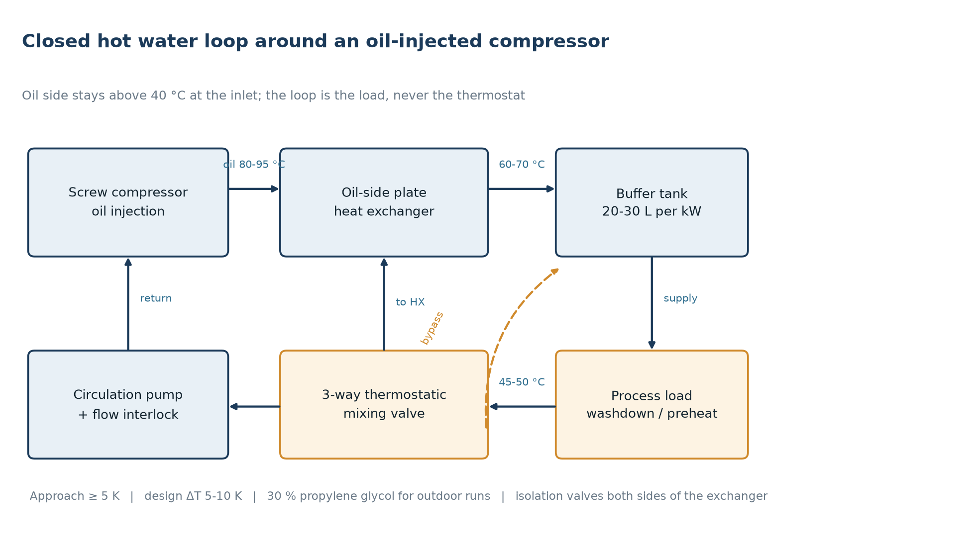
- Closed loop with a buffer tank. The default for industrial sites: a 5 to 10 K design difference, 20 to 30 litres of storage per kW of recoverable heat, a pump at 0.05 to 0.08 l/s per kW, and a three-way thermostatic valve holding oil inlet above 40 °C. The tank decouples load swings from demand.
- Boiler make-up preheat. The highest value per kWh, because it displaces fuel over a short loop. Never size it above the real make-up demand: more hot water than the boiler can absorb just raises the return temperature and the exchanger stops transferring heat.
The two temperatures that decide the design
Every heat recovery argument eventually reduces to two numbers: the oil temperature at the compressor inlet and the water temperature you are trying to reach. The first is a reliability limit, the second is a thermodynamics limit, and they pull in opposite directions.
| Parameter | Design value | Why |
|---|---|---|
| Oil discharge, full load | 80–95 °C | Sets the ceiling on water temperature |
| Oil inlet, minimum | 40 °C (45 °C preferred) | Below this, moisture stays in the oil instead of leaving with the air |
| Hot water supply | 55–70 °C | Oil discharge minus a 5–15 K approach |
| Hot water return | 45–50 °C | Keeps margin above the oil inlet floor |
| Heat exchanger approach | 5 K or better | A bigger exchanger buys temperature, not energy |
| Loop temperature difference | 5–10 K | A smaller difference means more flow and larger pipes |
The oil inlet floor is the one people ignore. An oil-injected element relies on the oil to seal clearances and carry heat away, and it relies on temperature to keep condensed water from accumulating in the sump. Run the oil at 35 to 40 °C for weeks and the water that enters with the intake air stays in the oil, forming an emulsion that accelerates acid formation and bearing wear. A recovery loop that is allowed to cool the oil below that floor has converted a saving into a repair.
So the water-side thermostat holds oil inlet at 45 °C rather than chasing maximum water output, and the loop delivers its rated temperature only while the compressor is loaded. A design that assumes full load all year promises roughly double what the site gets.
Sizing the exchanger and the buffer tank
Recoverable heat is close to 0.75 times shaft power at full load, scaled by the duty-weighted load rather than the nameplate. A 90 kW unit averaging 75 % load releases about 50 kW: size the exchanger for that, not for the 68 kW of a test bay.
Tank volume follows from how long the loop has to ride through a demand gap: V = Q × t / (4.186 × ΔT), with Q in kW, t in seconds and V in litres. Fifty kilowatts over a fifteen-minute gap at a 10 K difference is about 1,075 litres. Below that, the process sees the compressor’s load swings and the burner or the mixing valve cycles.
| Motor size | Recoverable heat at full load | Buffer tank (20–30 l/kW) | Pump flow (0.05–0.08 l/s per kW) |
|---|---|---|---|
| 37 kW | 28 kW | 560–840 l | 5.0–8.1 m³/h |
| 55 kW | 41 kW | 820–1,230 l | 7.4–11.8 m³/h |
| 75 kW | 56 kW | 1,120–1,680 l | 10.1–16.1 m³/h |
| 90 kW | 68 kW | 1,360–2,040 l | 12.2–19.6 m³/h |
| 132 kW | 99 kW | 1,980–2,970 l | 17.8–28.5 m³/h |
Keep oil-side pressure drop inside 0.3 to 0.5 bar and the water side inside 20 to 30 kPa. A gasketed plate unit is the default where hardness is unknown; brazed units fit inside the canopy on packaged machines. Whichever you use, put isolation valves and a drain on both sides so the plates can be cleaned without stopping production air.
Control: keep the oil above 40 °C or nothing else matters
A heat recovery loop is a small control problem with a large mechanical consequence. The sequence that works on site is short:
- A three-way thermostatic valve on the water return, set so oil inlet stays at 45 °C. It blends bypass water with cold return water; it does not throttle the compressor.
- A flow or differential pressure switch across the exchanger, interlocked to open the bypass and alarm on loss of flow. Water-side blockage is the one failure that can overheat a machine within minutes.
- Isolation valves and drains on both sides plus a water-side strainer, so cleaning does not need a shutdown.
- Thirty percent propylene glycol on frost-exposed runs, with pump and exchanger selected for the higher viscosity.
- Four logged temperatures: oil inlet, oil discharge, water supply, water return. Trends catch a fouling exchanger months before the process notices.
Failure modes we see on site
- Tank too small. The process sees every unloading cycle, the burner short-cycles, and the loop is blamed for being unreliable when it is only undersized.
- Return temperature drifting low in winter. Cold make-up water pulls the loop under the oil floor and the bypass never quite keeps up.
- No bypass when the process stops. Over a weekend the water side cools the oil to ambient and Monday’s start pulls moisture into the sump.
- Sized on nameplate, not on load. A plant at 55 % average load gets roughly half the recoverable heat the proposal assumed.
Estimating the saving without a price sheet
Avoided energy is the recoverable power times the hours of demand, divided by the efficiency of whatever you displace: 0.85 to 0.92 for a gas boiler, or the seasonal COP of a heat pump. Pumping energy is 3 to 5 % of what the loop recovers and belongs in the same sum.
| Annual demand hours | Recovered at 50 kW | Gas equivalent at 0.9 boiler efficiency |
|---|---|---|
| 2,000 h | 100,000 kWh | ≈ 111,000 kWh of gas |
| 4,000 h | 200,000 kWh | ≈ 222,000 kWh of gas |
| 6,000 h | 300,000 kWh | ≈ 333,000 kWh of gas |
Two caveats. The hours that count are hours of demand, not hours of running: a plant needing hot water for one shift cannot recover on the other two unless it stores. And a VSD machine’s recoverable power follows its load almost linearly, so a loop designed at full load looks excellent in January and mediocre in July. Both argue for measuring first: a week of logged load, discharge temperature and water demand answers more than a month of discussion.
Checklist before the loop is ordered
- Logged load profile for a full week, including nights and weekends.
- Water demand temperature, flow and hours, taken from the process rather than assumed.
- Oil discharge and oil inlet temperatures at the actual load, not at nameplate.
- Recoverable power calculated on the duty-weighted load, with a 20 % margin downward.
- Buffer tank volume from the ride-through time, and pump flow from the design ΔT.
- Bypass, thermostat setting and flow interlock drawn with the compressor schematic they protect.
Where the loop meets the rest of the plant
Three interactions are worth checking early. If several compressors run under a sequencer, pipe the loop to the machine carrying the base load: the trim machine lives at 30 to 50 % load and returns very little heat per hour, as described in parallel compressors and trim sizing. On drying, recovering aftercooler heat lowers the air temperature entering the dryer, which helps, but a colder inlet also condenses more water in the wrong place if the separator is undersized; the dew point you actually need is set out in dryer selection by pressure dew point. On a VSD machine the recoverable power tracks load directly, so the loop’s output is a by-product of the control strategy rather than the rating, which is the subject of part-load kWh savings on VSD compressors.
Two further points. Water-lubricated oil-free machines discharge much cooler, often 50 to 60 °C, so a practical loop reaches 40 to 50 °C water rather than 70 °C; dry screws discharge hotter but tolerate a cooling interruption less. And the pipework carrying 60 °C water must not force the compressed air main into a longer path, which is why the layout guidance in compressor room layout and piping pressure drop applies to the recovery loop as well.
Frequently asked questions
How much of the motor power can actually be recovered?
Between 85 and 94 % of the electrical input is available as heat, but the share you can deliver as useful hot water is normally 60 to 75 %, limited by the water temperature you need and by the hours the demand exists. At full load, plan on about 0.75 kW of recoverable heat per kW of shaft power; scale that down with load.
Can the loop make domestic hot water?
Yes, with a double-wall exchanger and a leak port, or with a separate exchanger dedicated to the potable side. Storage should stay at 60 °C or above, or be pasteurised periodically, and the potable circuit should never share a single-wall plate with the oil circuit.
Does heat recovery reduce compressor reliability?
Only in two ways: oil inlet temperature falling below about 40 °C, and loss of water flow without a bypass. Both are solved with a thermostatic three-way valve and a flow interlock. With those in place the loop is transparent to the machine and the compressor keeps its own temperature control.
What return temperature should I design for?
45 to 50 °C, which leaves margin above the 40 °C oil inlet floor. A colder return recovers slightly more energy per litre but takes the oil temperature with it on cold days; the extra energy is not worth the condensation risk.
Is heat recovery worth it on a VSD compressor?
Yes, provided the plant runs long hours with a real hot water demand. The recoverable power follows the load, so a VSD machine at 50 % average load returns about half the heat of the same machine at full load. The hours of demand matter more than the machine’s efficiency.
Answers apply to oil-flooded rotary screw installations with standard filtration; site-specific limits always come from the manual of the unit supplied and from the process standard for the application.
Sizing a loop for a specific site?
Send the machine size, a week of load data and the water temperature the process needs. We will work out the recoverable power, the tank volume and the exchanger duty, and mark the points where the loop has to protect the compressor.